PhotoStress® Analysis - Stress Analysis
Leading Distributor Of Cost Effective Testing And Measurement Solutions
|
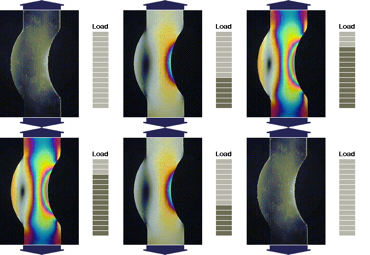
•Instant identification of stress concentrations and zero stressed areas
Reflection Photoelasticity White light generated by the light source propagates through a polarizer and quarter wave plate. The circularly polarized light then travels through a Photostress® coating (made of a photoelastic material) that has been bonded to the test piece with a special reflective adhesive. The light then travels back through an additional analyzer and quarter wave plate. The image is then captured with a digital video camera, and transferred to a computer equipped with the PSCalc® software which enables the user to store and process all the acquired data. System Components Model LF/Z-2 Basic Reflection Polariscope
Using PhotoStress® Analysis System
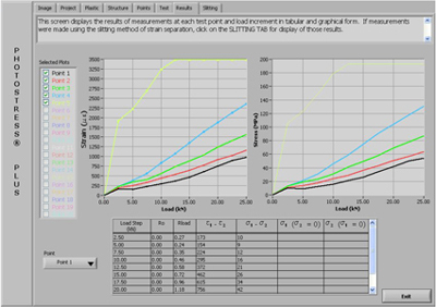
You can easily store and process data acquired from the digital video camera and the electronic compensator with the PSCalc software. By determining the material properties of both the photoelastic material and the test specimen, the numerical data from every tested point can be stored or processed to easily create project reports and visual images.
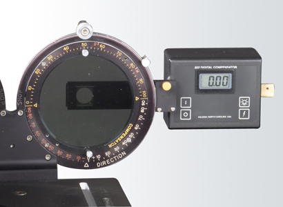
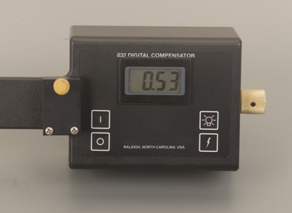
With the Model 832 Electric Compensator and the PSCalc computer software, measurement and calculation of stress/strain values is simple and quick. At the point of measurement, an initial no load (Ro) reading is made with the compensator. A second reading (R load) is then made after loading the part. After this, null balance readings are made and the numerical information is then electronically transferred to a computer configured with PhotoStress PSCalc software.
The principle strain directions are always measured with reference to an established line, axis, or plane. Therefore, the initial step for the determination of the direction of principle strains (or stresses) will be to select convenient reference. In most cases, the reference direction is suggested immediately, like an axes of symmetry of the test part or structure; in other cases, a vertical or horizontal line will suffice. When a plane polarized beam of light transverses a photoelastic coating on a part subjected to stress, it splits into waves propagating at different speeds along the directions of principle strains. After emerging from the plastic, these two waves will be out of phase with one another and will not recombine into a single vibration parallel to the one entering the plastic. However, at points where the direction of the principle stresses are parallel to the axes of polarizing filter, the beam will be unaffected and the emerging vibration will be parallel to the entering one. An analyzing filter with its axis perpendicular to the polarizing filter will reproduce extinction of the vibration at these points.
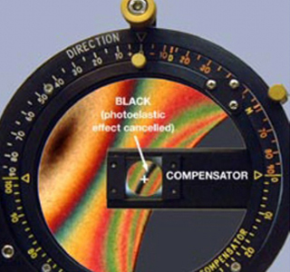
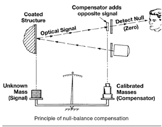
Null balance compensation operates on the principle of introducing into the light path of the polariscope a calibrated variable birefringence of the opposite side to that induced in the photoelastic coating by the strain field. When the opposite sign variable birefringence is adjusted to precisely match the magnitude of the strain induced birefringence, complete cancellation will occur, and the net birefringence in the light path will be zero. The condition of zero net birefringence is easily recognized because it produces a black fringe in the isochromatic pattern where, before introducing the compensating birefringence, a color fringe existed. The device is synthesizing a calibrated birefringence is known as a null balance compensator.
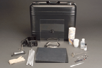
Calibration of high-sensitivity photoelastic coating materials such as polycarbonates and the rigid epoxies is usually accomplished by employing a cantilever beam in bending. The coating is placed on one side of the beam, and the beam is strained by dead weights or a predetermined deflection F applied on the free end. Accurate measurement of the fringe order N with a reflection polariscope at a number of increments of load, will generate graph of F versus N, and best fit straight line is constructed through the data points. The slope of this line gives the best value N/F to be used for the calibration constant. For further reading, click here for Calibration of PhotoStress® Coatings (Technical Note TN-701). Calibration Kit (comes as a part from the PhotoStress basic kit), includes:
PhotoStress® Technology An extensive technical background is also available: Technology:
Application Techniques:
Product Usage: Coatings and Adhesives
Case Studies:
Animated Demonstration:
|
 Main Benefits and Solutions
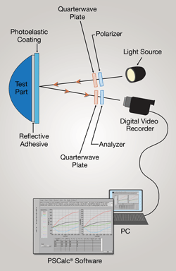 System Configuration



 Calibration Process